|
|
|
|
|
|
|
|
|
|
|
|
|
|
|
|
|
|
|
|
|
|
|
|
|
It's about time that you were given a practical example of all this. The following shows how we can construct a circuit that is found in the heart of every processing chip - a circuit to perform binary addition. If you need an introduction to binary numbers and binary addition, click here.
|
|
|
|
| |||||||
|
|
|
|
|
|
|
|
| |||
|
|
|
|
| |||||||
|
|
|
|
| |||||||
|
|
|
|
| |||||||
|
|
||||||||||
The reason that I write the 1 produced when 1 is added to 1 under the line is that there may be another column of figures to the left of this column. In this case, the 1 that is produced will be a carry out that affects the figures in the next column. Here is the last part of that calculation again, this time as part of a larger calculation:
|
|
|
| |
|
|
|
|
|
|
| |||
|
|
|
|
|
|
| |||
|
|
|
||
A circuit that performs the addition of two binary digits like this is called a half adder (I'll explain why we say "half" in the next section). A half adder can only add two binary digits. If you wanted a long binary number added to another long binary number, you would use several circuits (termed "full" adders in this case), each of which handles one digit of each number, all connected end to end - see the next section.
In fact, the binary addition of two digits always produces two numbers - the sum of those digits and a carry out digits which is then added to the next column along, assuming there is one, or which just disappears into the void. Here is that first diagram again with both the sum digit and the carry out digits explicitly listed:
 |
|
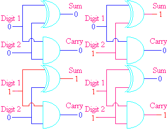
You will notice that the sum digit has exactly the same truthtable as an XOR gate and the carry digit has exactly the same truthtable as an AND gate. This means that the binary half adder circuit just consists of two gates:

The small loop drawn just in front of the two gates shows two wires which cross without connecting, i.e. there is no connection between the Digit 1 input and the Digit 2 input.
Here is a column which has been extracted from the middle of the sum somewhere. You will notice that a there is a carry digit underneath the column itself, as well as one under the next column. Now, including the carry in, there are 8 possible combinations of inputs, and I have listed them all:

Again, we just turn this into a truthtable. However, there are now three inputs, called Digit1, Digit2 and Carry In, and two outputs, called Sum Digit and Carry Out:
|
|
|
|
|
|
|
|
|
|
|
|
|
|
|
|
|
|
|
|
|
|
|
|
|
|
|
|
|
|
|
|
|
|
|
|
|
|
|
|
|
|
|
|
|
|
|
|
|
|
|
|
|
|
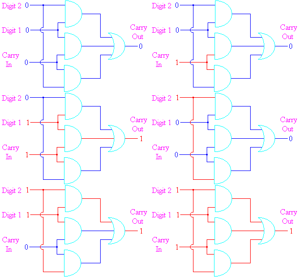
The easiest way to turn this into a circuit is to imagine the table split into a top half and a bottom half. The top half of the table occurs when the Digit 1 input is 0. In this case, the Sum digit is equivalent to an XOR gate and the Carry Out digit is equivalent to an AND gate. The bottom half of the table occurs when the Digit 1 input is 1. In this case, the Sum digit is the opposite of the XOR (i.e. equivalent to an Exclusive OR with the output inverted) and the Carry Out digit is equivalent to an OR gate. This would give a circuit as follows:


Although there are really only three inputs to the circuit, we have written each of the inputs twice (once for the Sum Digit and once for the Carry Out). Don't be put off by this - just assume that both the lines marked "Digit 1" are connected to the same input, that both the lines marked "Digit 2" are connected to the same input and that both the lines marked "Carry In" are connected to the same input.
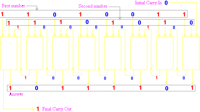
In practice, there's not a great deal that you can do with adding a single pair of digits. We duplicate the circuit that you see above several times (8 times, 16 times or 32 times - usually a power of 2) to form a proper binary adder:

In this diagram each of the yellow rectangles represents one instance of the circuit that we developed above. It has two digit inputs and a Carry In input which is the Carry Out output from the previous column. Each Carry Out output is then connected to the Carry In input of the next column. The initial Carry In input is fed from a binary digit called the Carry Flag, which is usually set to 0 (The Carry Flag is used to perform multi-byte addition - see the section on Computer Architecture). The final Carry Out output is fed back into the Carry Flag for use later on.
In the example given in the diagram, the two numbers being added are 11010011 and 11101010. They produce an answer which is 10111101 with a final Carry Out. This is equivalent to adding the decimal numbers 211 and 234 and getting the answer 189. I realise that 211 + 234 is not 189, but this has happened because the answer has "overflowed" off the end of the adding unit, and the fact that a Carry Out was produced from the final calculation indicates that the real answer should be (256) + 189 = 445. Unfortunately, this adding device is an 8-bit device which cannot produce answers larger than 255, so it sets the Carry Flag at the end to indicate that there is a 256 missing from the answer.
Incidentally, the same circuit can be used to perform subtraction, except the number to be subtracted is inverted (all the bits are reversed, so 1 becomes 0 and vice-versa) and 1 is added to it.
 Go back |
 Main Menu |
 Questions |
 Go on |